SPI Guide
Introduction#
WizFi360 operates in SPI slave mode and can be controlled via AT commands. In order to communicate with the MCU, the SPI pins must be connected and set the SPI_EN(PB13) pin to Low for SPI. Refer to Figure 1. WizFi360 Pinout to locate the SPI pins. Set the SPI_INT(PB14) pin to low when the user needs to send data from WizFi360 so that the SPI master can read the data.
Pinout#
SPI pins are from PB13 to PB17 in the below Figure WizFi360 Pinout.

SPI Frame Format#
WizFi360 is controlled by the SPI frame format sent from the SPI master. The SPI frame is controlled by CSn and composed of SPI Control Frame, AT CMD Frame, and DATA Frame . DATA Frame composed RX DATA Frame and TX DATA Frame. Users can select the default status, buffer save size, CMD, DATA SEND, and DATA RECEIVE during the control phase.
SPI Control Frame#
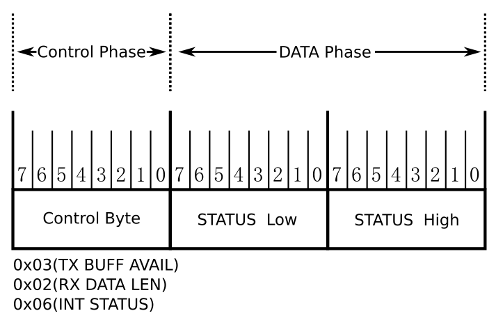
TX BUFF AVAIL, RX DATA LEN, and INT STATUS must be read before users write or read data into WizFi360. The SPI Control Frame sends 1Byte of control byte and reads 2Byte of status data.
- 0x03(TX BUFF AVAIL) : checks whether the peer buffer is ready to write date before transmission.
- 0x02(RX DATA LEN) : reads the data length accumulated in the peer buffer before the data is received.
- 0x06(INT STATUS) : reads the interrupt status of slave.
SPI Control Frame
SPI Timing Graph (SPI Control Frame)

AT CMD Frame#
The AT CMD frame reads the TX BUFF AVAIL from the SPI Control Frame and sets the Control Byte as 0x91 during the Control Phase if 0x0002 or bit 2 is high. Then the CMD length is set in units of 4bytes and AT CMD messages are included in the data for transmission. AT CMD reply uses the RX Data Frame method when receiving data. Please refer to the AT instruction set for more details on AT-CMD.
AT CMD Frame

SPI Timing Graph (AT CMD Frame)

Data Frame#
TX Data Frame#
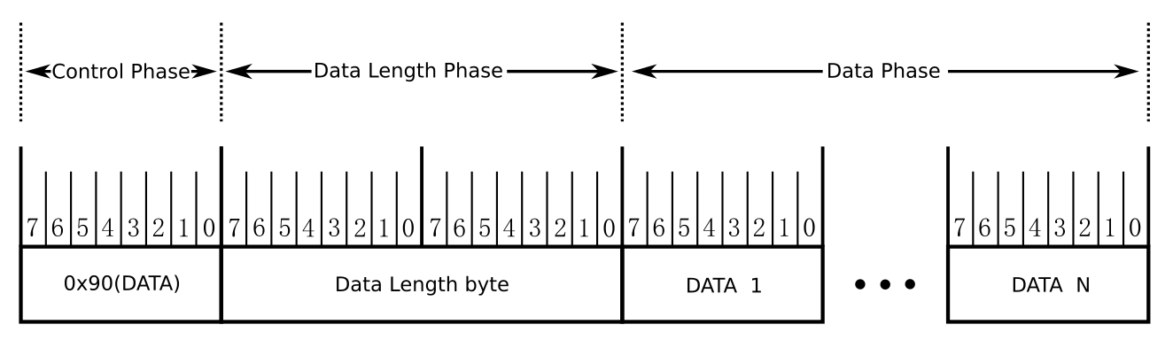
AT+CIPSEND, AT+CIPSENDEX, and AT+CIPSENDBUF must be transmitted from the AT CMD Frame and users must follow the next steps to prepare TCP or UDP data transmission in DATA trans mode. The TX data frame reads the TX BUFF AVAIL from the SPI Control Frame and sets the Control Byte as 0x90 during the Control Phase if 0x0002 or bit 2 is high. Then the CMD length is set in units of 4bytes and DATA messages are included in the data for transmission. DATA reply uses the RX Data Frame method when receiving data.
TX Data Frame
SPI Timing Graph (TX DATA Frame)

RX Data Frame#
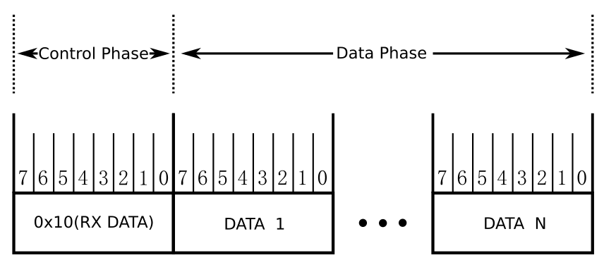
When a reply or data is received after the AT CMD Frame is transmitted, check whether the interrupt pin is low or not. If the interrupt pin is low, users read the value of INT STATUS using the SPI Control Frame. If the value of INT STATUS is 0x0002 or bit 2 is high, users read the value of RX DATA LEN using the SPI Control Frame. And if the value of RX Data Len is not zero, users set the Control Byte as 0x10 during the control phase and read data. The total data count is the value of RX DATA LEN.
RX Data Frame
SPI Timing Graph (RX Data Frame)

Operation#
AT CMD Operation#
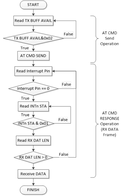
Use AT CMD to set WizFi360 or follow the steps below to set SEND mode and request data.
AT CMD Operation Flowchart
Data Operation#
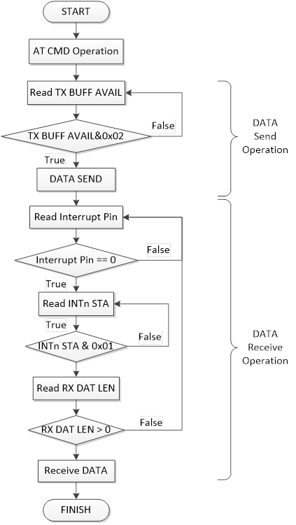
Data can be sent if AT+CIPSEND, AT+CIPSENDEX, OR AT+CIPSENDBUF is entered in AT CMD or in DATA TRANS mode.
DATA Operation Flowchart