WizFi360-EVB-Shield
Overview#
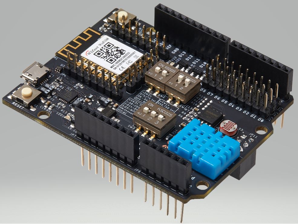
This document describes WizFi360-EVB-Shield. WizFi360-EVB-Shield is a development board for experiment, test and verification of WizFi360. WizFi360-EVB-Shield can also be used as an Arduino shield. WizFi360 is a low cost and low-power consumption industrial-grade WiFi module. It is compatible with IEEE802.11 b/g/n standard and supports SoftAP, Station and SoftAP+Station modes. The serial port baud rate can be up to 2Mbps, which can meet the requirement of various applications.
Features#
- WizFi360
- WiFi 2.4G, 802.11 b/g/n
- Support Station / SoftAP / SoftAP+Station operation modes
- Support “Data pass-through” and “AT command data transfer” mode
- Support serial AT command configuration
- Support TCP Server / TCP Client / UDP operating mode
- Support configuration of operating channel 0 ~ 13
- Support auto 20MHz / 40MHz bandwidth
- Support WPA_PSK / WPA2_PSK encryption
- Serial port baud rate up from 600bps to 2Mbps with 16 common values
- Support up to 5 TCP / UDP links
- Obtaining IP address automatically from the DHCP server (Station mode)
- DHCP service for Wireless LAN clients (AP mode)
- Support DNS for communication with servers by domain name
- Support “Keep-Alive” to monitor TCP connection
- Support “Ping” for monitoring network status
- Built-in SNTP client for receiving the network time
- Support built-in unique MAC address and user configurable
- Support firmware upgrade by UART Download / OTA (via WLAN)
- Industrial grade (operating temperature range: -40 ° C ~ 85 ° C)
- CE, FCC certification
- ETC
- Built-in UART to USB chip
- CP2104-GM
- Micro USB B Type Connector
- UART Selector
- JP1, JP2, JP3
- 2.54mm Pin Header
- Built-in Sensors
- Temprature/Humidity Sensor: DHT11
- CDS Sensor: GL5537
- Built-in Tact Switchs
- System Reset Switch: S1
- WiFi Reset Switch: S2
- Built-in LED Indicators
- D13 LED
- Built-in Level Shifters
- The voltage of the RXD/TXD signal changes according to the main board platform voltage.
- Built-in DIP Switchs
- UART RXD/TXD Selector: SW1
- UART RTS/CTS Selector: SW2
- Sensor/RESET Pins Selector: SW3
- Built-in UART to USB chip
Quick Start Guide#
Datasheet#
Technical Reference#
Ref Schematic & Other Board Schematics#
Library#
ETC#
Serial Port Driver#
CP210x USB to UART Bridge VCP Drivers